写真のように繰り返し表示します。
仕様書(英語)はこちら
/****************************************************************************/ /* Standard Fieald Sequential LCD Module Test Program */ /* MPU Device:PIC16F690 on PicKit2DemoBoard */ /* LCD module:SDK8A4302A */ /* COPYRIGHT:SANTECH DISPLAY CO.,LTD. 2007/07/01 */ /****************************************************************************/ /* PIC16F690 */ /* +-------U-------+ */ /* +5V===|Vdd VSS|===GND */ /* OSC1-->|RA5 RA0|<-- */ /* OSC2<--|RA4 RA1|--> */ /* +5V===|/MCLR RA2|--> */ /* DB5<--|RC5 RC0|---DB0 */ /* DB4<--|RC4 RC1|---DB1 */ /* DB3<--|RC3 RC2|---DB2 */ /* DB6<--|RC6 RB4|---busy */ /* DB7<--|RC7 RB5|---cs */ /* ---|RB7 RB6|---clk */ /* +---------------+ */ /* */ /****************************************************************************/ #include<16F690.h> #fuses HS,NOWDT,PUT,NOPROTECT #use delay(clock=20000000) #use fast_io(B) #use fast_io(C) /***PIN DEFINE***************************************************************/ #bit busy=0x06.4 //PortB of address is 0x06 #bit cs=0x06.5 #bit clk=0x06.6
// Display DATA:15sirialDATA(15*2segments)+「0xfa」 
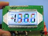
int s1[16]={0x60,0x43,0x21,0x01,0x23,0x45,0x65,0x43,0x21,0x01,0x23,0x45,0x65,0x43,0X21,0xfA}; //Colorfull 
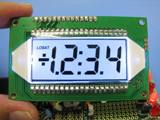
int s2[16]={0x00,0x00,0x00,0x07,0x70,0x70,0x00,0x00,0x70,0x07,0x00,0x70,0X00,0x07,0x00,0xfA}; //all black(1.2:3.4) 
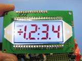
int s3[16]={0x44,0x44,0x44,0x47,0x74,0x74,0x44,0x44,0x74,0x47,0x44,0x74,0X44,0x47,0x44,0xfA}; //all red(1.2:3.4) 
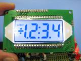
int s4[16]={0x22,0x22,0x22,0x27,0x72,0x72,0x22,0x22,0x72,0x27,0x22,0x72,0X22,0x27,0x22,0xfA}; //all blue(1.2:3.4) 
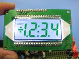
int s5[16]={0x11,0x11,0x11,0x17,0x71,0x71,0x11,0x11,0x71,0x17,0x11,0x71,0X11,0x17,0x11,0xfA}; //all green(1.2:3.4)
int *ptr; //ポインタ宣言 /*******************************************************************************/ void fs_dat(ptr) //ポインタ変数から液晶を表示させる関数、これがキモ! { int i; //for文用繰り返し変数 while(busy==1){} //Busy Check cs=0; delay_us(4); for(i=0;i<16;i++) { output_c(*ptr); clk=1;delay_us(16); clk=0;delay_us(16); ptr++; }
cs=1;delay_us(15); } /******************************************************************************/ main(){ set_tris_c(0x00); //PortC is all output mode set_tris_b(0x10); //busy(RB4)is input mode , other B-ports are output mode delay_ms(25); //電源投入時及びリセット時の安定性確保 while(1) { fs_dat(s1);delay_ms(1000); //配列をポインタとして代入してfs_dat()を実行 fs_dat(s2);delay_ms(1000); fs_dat(s3);delay_ms(1000); fs_dat(s4);delay_ms(1000); fs_dat(s5);delay_ms(1000); } }